Introduction
Industrial LCD pressure damage is a class of display defects caused by mechanical stress coupling into the LCD stack—often through the bezel, enclosure, or mounting features. In uptime-critical systems (factory HMIs, mobile machinery, field instruments, kiosks, edge gateways), these defects matter because they can:
reduce readability and operator confidence
trigger misinterpretation of alarms or setpoints
increase service calls and unplanned downtime
recur after “simple” panel replacement if the root cause is in the mechanics
This guide is for engineers, integrators, and operations teams who need practical ways to identify pressure damage early, separate it from look-alike failures, and harden the mechanical stack-up so it doesn’t come back.
You’ll learn the most common causes, how to diagnose them in the field, which tests and ratings actually relate to the failure modes, and a prevention checklist you can carry into design reviews and assembly work instructions.
Pressure Damage Basics (industrial LCD pressure damage)
LCD stack and stress paths
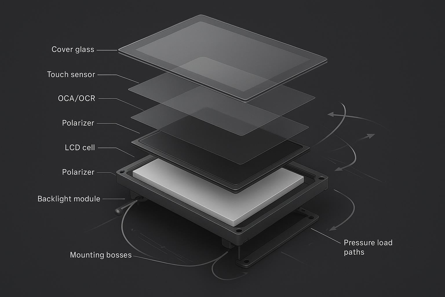
An industrial display is not a single piece of glass—it’s a layered optical-mechanical system. A typical stack looks like:
cover lens or protective window (glass or polycarbonate)
touch sensor (PCAP or resistive), with its own substrate and perimeter constraints
bonding layer (air gap, OCA/OCR/LOCA, or frame adhesive)
LCD module: polarizers + liquid crystal (LC) cell + driver bonding (COF/COG)
backlight and optical films (diffuser/prism sheets)
metal frame, brackets, and mounting bosses/standoffs
Mechanical stress can enter this stack through multiple paths:
bezel clamping: fasteners or clips create localized compression
frame warp: a non-flat mounting surface forces the module to bend to match it
torsion: enclosure twist transfers bending into the display opening
impact or handling loads: concentrated forces at edges/corners or through cable strain
When stress reaches the LCD cell or the optical film stack behind it, it often shows up as localized luminance changes (mura), bright spots, dark blotches, or lines.
⚠️ Warning: If a pressure artifact appears after installation (not at incoming inspection), treat the enclosure/mounting as the first suspect—not the LCD supplier.
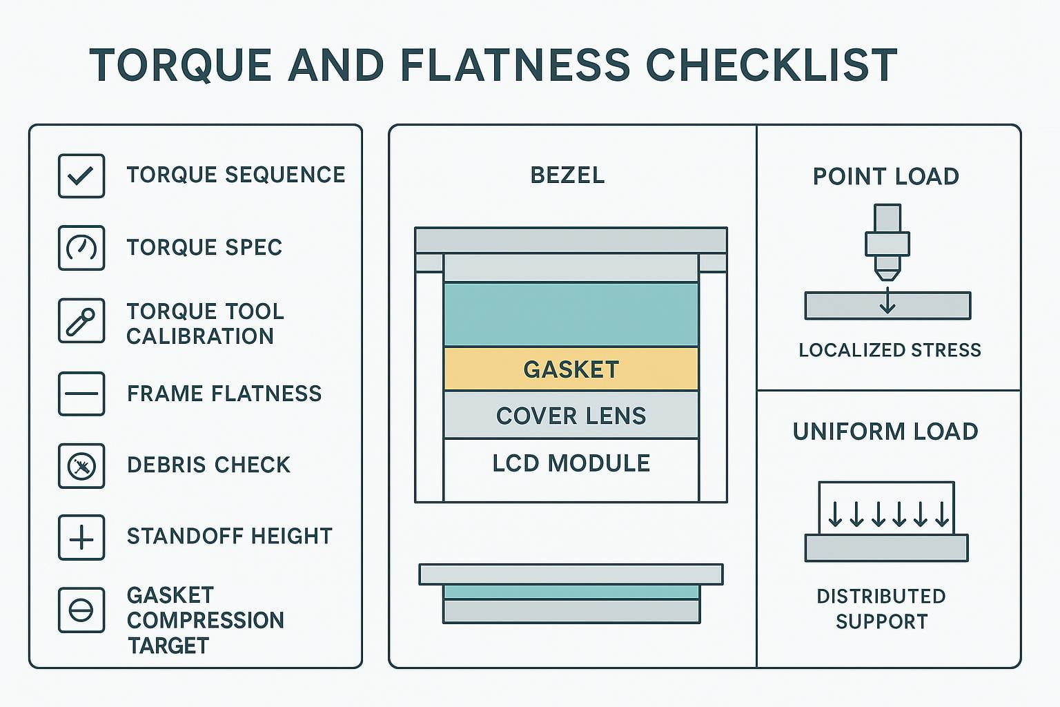
Point load vs uniform load
The difference between a display that survives and one that develops pressure marks often comes down to how force is distributed.
Point load: a small contact area carries the load (a trapped particle, a proud boss, a sharp bezel edge, a standoff that’s too tall). Point loads create high local stress and are the most common trigger for “one bright spot” or a sharply bounded mura region.
Uniform load: force is spread over a larger area (compliant gasket, controlled compression, load-spreading frame). Uniform loads reduce peak stress even when total clamp force is similar.
In practice, you can clamp “too hard” and get away with it if the load is well distributed—and you can clamp “gently” and still fail if one corner is carrying most of the load.
Typical artifacts (mura, spots, lines)
Pressure damage in LCDs commonly presents as:
mura / clouding: non-uniform patches visible on mid-gray backgrounds (often described as LCD mura pressure marks)
bright or white spots: localized light leakage or film deformation that’s easiest to see on dark backgrounds
lines: straight or slightly curved bands that may align with bezel edges, bosses, or frame ribs
A useful field clue: pressure artifacts are often more obvious at certain viewing angles and under uniform backgrounds (dark gray, light gray, solid colors).
Industrial Causes
Bezel torque, non-flat frames, debris
Many pressure failures start at the interface you can control the most: the bezel and mounting frame.
Common causes include:
uneven screw torque that pulls one side down harder than the others (a classic path to bezel torque display mura)
non-flat frames (weld distortion, machining tolerance stack-up, bent sheet metal) that force the display to conform
sharp bezel edges or narrow contact lands that concentrate force
debris trapped between bezel/gasket and the cover lens—turning a “uniform clamp” into a point load
Even reputable guidance on industrial display defects notes that rigid or uneven mounting structures and assembly pressure concentrations are frequent contributors to white-spot/pressure-mark issues in the field (see the practical causes described in White Spot on LCD Displays: Causes & Prevention).
Enclosure twist, thermal mismatch, vibration
Industrial enclosures aren’t always stiff, and the display opening is a stress concentrator.
Watch for:
torsion in the enclosure (door-mounted HMIs, vehicle-mounted displays, long cantilevered panels)
thermal expansion mismatch between the cover lens, bezel, and frame—especially across wide temperature swings
vibration that “works” the stack over time, turning marginal compression into recurring stress
If pressure marks appear only after temperature cycling or only after shipment, suspect a combination of thermal mismatch and vibration loosening the intended load path.
Handling, cable strain, direct impacts
Not all pressure damage is “design.” Some is introduced during build, rework, or service.
Typical contributors:
lifting the assembly by the glass instead of the frame
prying the bezel during rework
cable routing that puts a bending moment into the display PCB or module frame
edge/corner impacts (especially damaging because they can couple into the LC cell and the backlight film stack)
When investigating, include a simple question: When did the defect first appear—at incoming inspection, after integration, after shipment, or after months in the field? The timeline often narrows the cause faster than microscope work.
Diagnosis & Inspection
Visual checks under uniform backgrounds
You don’t need specialized metrology to find pressure damage—you need a repeatable inspection setup.
A practical checklist:
Warm up the display to a stable operating state.
Display uniform backgrounds: black, 20–30% gray, 50% gray, and white.
Inspect at normal viewing distance and then closer, at multiple angles.
Record with a camera only after you’ve stabilized exposure; otherwise, photos can exaggerate or hide mura.
If possible, compare to a known-good unit under the same test pattern and brightness setting.
Inspection acceptance criteria (field-ready)
Because pressure artifacts are angle- and background-dependent, accept/reject decisions should be tied to repeatable viewing conditions—not a quick glance.
Use this as a practical baseline, then align it to your internal quality standard:
Stabilize conditions: warm up the display, set a fixed brightness, and disable auto-dimming.
Viewing geometry: inspect at normal operating distance and at typical operator angles; then repeat at a shallow angle where mura tends to “pop.”
Test patterns: include black, dark gray, mid-gray, light gray, and white. If you have it, add a uniform color sweep.
Lighting: note ambient lighting (factory lighting, direct sun, etc.). The same panel may look acceptable in one environment and unacceptable in another.
Define your acceptance criteria in simple, auditable terms:
Location-based criteria: specify whether artifacts in critical UI zones (alarms, safety prompts, setpoints) are automatically rejectable.
Stability criteria: if the defect changes noticeably with small changes in bezel compression (safe, controlled check), treat it as pressure-related and require a mechanical root-cause fix before replacement.
Progression criteria: if the artifact grows with temperature cycling or time in service, treat it as a reliability risk even if it is initially subtle.
Note: This article provides engineering best practices, not a universal cosmetic specification. For production acceptance, set criteria that match your application risk (e.g., safety-critical HMIs vs. non-critical kiosks) and verify with your display supplier’s optical inspection standard.
Photo documentation protocol (so images are comparable)
Photos of mura/pressure spots are often misleading unless the setup is controlled.
Lock exposure, white balance, and focus (manual mode if possible).
Capture the same set of patterns at the same brightness.
Take at least two angles: straight-on and one shallow angle.
Include one reference shot of a known-good unit under identical settings when available.
Record the build context in the filename or notes: unit ID, torque sequence used, gasket revision, assembly date, and when the defect first appeared.
This turns “a bad photo” into evidence you can use to correlate artifacts with torque, flatness, debris, shipping, or thermal cycling.
Differentiate pressure marks, burn-in, ingress
Pressure damage has look-alikes. Differentiating early prevents wasted RMAs.
Pressure marks / mura: often visible on grays; can change with angle; may correlate to bezel edges, screw locations, or bosses.
Burn-in / image retention: typically tied to static UI elements. It tracks content history more than mechanical features. If the artifact resembles prior icons or high-contrast UI regions, treat it as retention first.
Moisture ingress / delamination: can show edge haze, bubbles, Newton rings, or progressive edge-to-center growth depending on seal/bond condition. The pattern often follows the perimeter seal geometry rather than screw locations.
If the artifact moves or changes when you slightly loosen the bezel (controlled, safe conditions only), that strongly implicates pressure. If it does not change at all with mechanical relaxation, broaden the hypothesis.
RMA vs field-repair decision gates
Use decision gates to avoid swapping the display when the enclosure will simply re-damage the replacement.
Field-friendly gates:
Single unit, cosmetic, stable, no safety impact: consider monitoring if acceptable for the application.
Multiple units show the same spot in the same location: treat as a mounting/flatness/process issue; stop replacing panels until mechanics are corrected.
Defect grows with time/temperature or affects readability/safety: escalate.
Any sign of cracked glass, fluid ingress, or compromised seal: RMA (field repair risks recurring failures and warranty conflicts).
A simple rule: if you can’t define the mechanical root cause and correct it, an RMA may restore function but won’t restore reliability.
Tests, Standards & Ratings
IEC 60068 vibration/shock/thermal-humidity
The IEC 60068 family is a core reference for environmental testing of electrotechnical products. It’s a collection of test methods, not a single “passed IEC 60068” badge (overview: IEC 60068 environmental testing series).
For pressure-damage risk, the most relevant categories are:
vibration (sinusoidal and random) that can amplify marginal mounting designs—think of it as your baseline for an IEC 60068 display vibration test approach
mechanical shock that can introduce transient point loads
temperature change / thermal cycling that drives CTE mismatch stresses
damp heat that can interact with bonding/seals (especially if delamination is a competing failure mode)
The important engineering point: these tests can reveal whether your mounting stack-up survives stress without developing optical artifacts, but only if the test setup mirrors your actual load path (mounting method, torque, gasket compression, enclosure stiffness).
MIL-STD-810 shock/vibration context
MIL-STD-810 is best understood as a framework for environmental engineering considerations and lab test methods, where the value comes from tailoring the test to the expected life-cycle exposures (overview: MIL-STD-810).
For industrial displays, it’s useful as a common language for shock/vibration/thermal methods—especially when your equipment will see transport shock, vehicle vibration, or rough handling. But “tested to MIL-STD-810” only means something when you know:
which methods were used
what levels and durations were applied
how the unit was mounted during the test
what the pass/fail criteria were (including optical acceptance criteria like mura limits)
In other words: treat MIL-STD-810 as context for building a defensible qualification plan, not as a shortcut label for ruggedness.
IK impact rating and point-load checks
IK ratings (IEC 62262) classify how well an enclosure resists external mechanical impact (standard landing page: IEC 62262: IK code). In practice, IK codes map to impact energies (J) used in standardized tests.
IK matters for industrial displays because cover windows and front bezels often need to resist knocks and impacts. But be careful with interpretation:
an enclosure can pass an IK impact test and still allow internal point loads that damage the LCD stack
IK primarily speaks to the enclosure’s impact resistance, not to the LCD cell’s tolerance to localized compression or frame twist
So pair IK requirements with point-load and mounting validation: verify that typical impacts don’t transfer stress into the LCD stack in ways that create mura, spots, or lines.
Prevention Best Practices
Compliant mounts, torque and flatness control
Pressure damage prevention is mostly mechanical discipline.
Best practices that pay off quickly:
Design for compliance: allow controlled “give” (gaskets, floating features, compliant brackets) so the display isn’t the stiffest element in the stack.
Control torque, not just “tightness”: define torque specs, sequence, and tools; document them.
Control flatness: measure the mounting frame flatness where the display actually sits (not a distant datum) and define acceptable limits.
Control standoff height: proud bosses create point loads; recessed bosses can over-compress gaskets when fasteners bottom out.
Debris control: treat the bezel-to-glass interface like an optical assembly—cleaning and inspection matter.
A practical strategy is to treat the display opening as a “precision interface” with its own work instruction: cleaning, inspection, torque sequence, and go/no-go checks.
Gaskets, spacers, and optical bonding (OCA)
Gaskets and spacers aren’t just for IP rating—they’re also force-shaping tools.
Gaskets can distribute load if compression is controlled and the gasket geometry supports uniform contact.
Spacers can prevent over-compression and protect sensitive regions (like corners and connector areas).
Optical bonding (OCA/OCR/LOCA, depending on the stack) can reduce internal reflections and eliminate air gaps, but it also changes how stress couples between the cover lens and the LCD module.
Two practical rules:
Don’t bond your way out of bad mechanics. If the bezel/frame is non-flat or torque is uncontrolled, bonding can transmit stress more efficiently into the LCD stack.
Use bonding to stabilize the stack once the load path is clean. When mounting is controlled, bonding can help distribute pressure and reduce micro-movement under vibration.
Emerging materials and methods
As rugged HMI designs mature, teams are adding more “mechanical forgiveness” to prevent point loads from ever reaching the LCD cell.
Approaches that are gaining traction:
Compliant perimeter adhesives tuned for stress relief (so the cover lens can move microscopically without concentrating force into one edge)
Floating bezel concepts that decouple enclosure twist from the display stack
Load-spreading frames that increase contact area without increasing total clamp force
Better control of bondline thickness in bonding processes, reducing stress gradients
As a non-promotional example, LMTEK describes rugged optical bonding and integration options that focus on spreading load and improving durability in industrial touch stacks (see LMTEK).
The key engineering point is not the supplier—it’s the method: use compliant interfaces and controlled stack-up geometry so the display sees distributed loads, not localized point forces.
Conclusion
Industrial LCD pressure damage is rarely “mysterious.” It usually traces back to a load path: bezel torque, frame flatness, trapped debris, enclosure twist, or a handling/impact event that introduced a point load into a layered optical stack.
The most reliable workflow links three pieces together:
causes (where stress is introduced)
diagnostics (how you detect and differentiate it from burn-in or ingress)
qualification (how vibration/shock/thermal cycling can expose marginal mounting before field deployment)
Immediate next steps that typically reduce recurrence:
Build a repeatable inspection setup (uniform backgrounds, controlled exposure, angle checks).
Add torque/sequence/flatness controls to your assembly process—and treat the display opening as a precision interface.
Create an environmental cycling plan that matches your real mounting method and acceptance criteria, using standards families like IEC 60068 as a framework.
If you’d like a second set of eyes on a specific mounting stack-up (bezel geometry, gasket compression targets, standoff scheme, and bonding approach), you can use LMTEK’s integration resources as a reference point—start with the custom TFT display bonding options and the applications library.